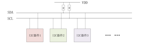
I2C 简介 I2C 是很常见的一种总线协议,它是 NXP 公司设计的,I2C 使用两条线在主控制器和从机之间进行通讯。一条是 SCL(时钟线),另外一条是 SDA(串行数据线),这两条线使用时需要接入上拉电阻,总线空闲时 SCL 和 SDA 处于高电平。I2C 总线标准模式下速度可以达到 100kb/s,快速模式下可以达到 400kb/s。I2C 总线工作是按照一定的协议来运行的,接下来我们看一下 I2C 协议。
图 1 I2C 总线多设备
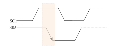
接下来我们看一下 I2C 协议有关的东西1、起始位
图 2 I2C 起始位
2、停止位
图 3 I2C 起始停止
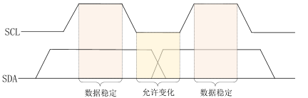
3、数据传输
图 4 I2C 数据传输
4、应答信号
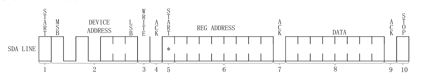
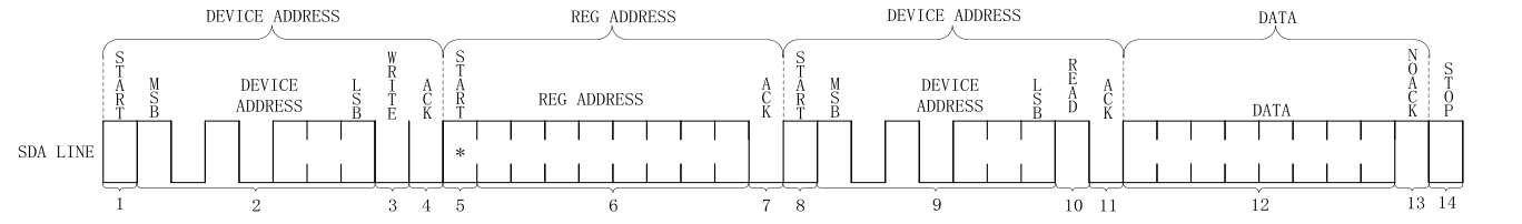
5、I2C 写时序
图 5 I2C 写时序
其具体步骤如下:
6、I2C 读时序
图 6 I2C 读时序
I2C 单字节读时序要比写时序复杂一些,分为四大步,第一步是发送设备地址,第二步是发送要读取的设备地址,第三部重新发送设备地址,最后一步就是 I2C 从器件输出要读取的寄存器值。具体是以下步骤:
Linux I2C 驱动模型 Linux 将 I2C 驱动分为两部分,一个是 I2C 总线驱动,就是针对 SOC 的 I2C 控制器驱动,也叫做 I2C 适配器驱动;另一个是 I2C 设备驱动,也就是针对具体的 I2C 设备而编写的驱动。
I2C 总线驱动 首先我们学习一下 I2C 总线驱动。在之前学习 platform 的时候就知道,platform 是虚拟出来的一条总线,目的是实现总线、设备、驱动框架。而对于 I2C 而言,不需要虚拟出一条总线,直接使用 I2C 总线即可。I2C 总线驱动的重点是 I2C 适配器(也就是 SOC 的 I2C 接口控制器)驱动。这里有两个重要的数据结构:i2c_adapter 和 i2c_algorithm,Linux 内核将 SOC 的 I2C 适配器抽象成 i2c_adapter,其定义在 include/linux/i2c.h 中,结构体内容如下
1
2
3
4
5
6
7
8
9
10
11
12
13
14
15
16
17
18
19
20
21
22
23
24
25
26
27
28
29
30
31
32
33
34
35
36
struct i2c_adapter { struct module *owner ; unsigned int class ; const struct i2c_algorithm *algo ; void *algo_data; const struct i2c_lock_operations *lock_ops ; struct rt_mutex bus_lock ; struct rt_mutex mux_lock ; int timeout; int retries; struct device dev ; unsigned long locked_flags; #define I2C_ALF_IS_SUSPENDED 0 #define I2C_ALF_SUSPEND_REPORTED 1 int nr; char name[48 ]; struct completion dev_released ; struct mutex userspace_clients_lock ; struct list_head userspace_clients ; struct i2c_bus_recovery_info *bus_recovery_info ; const struct i2c_adapter_quirks *quirks ; struct irq_domain *host_notify_domain ; struct regulator *bus_regulator ; struct dentry *debugfs ; DECLARE_BITMAP(addrs_in_instantiation, 1 << 7 ); };
其中,i2c_algorithm 类型的指针变量 algo 就是 I2C 适配器与 I2C 设备进行通信的方法,其定义在 include/linux.i2c.h 中,内容如下:
1
2
3
4
5
6
7
8
9
10
11
12
13
14
15
16
17
18
19
20
struct i2c_algorithm { int (*master_xfer)(struct i2c_adapter *adap, struct i2c_msg *msgs, int num); int (*master_xfer_atomic)(struct i2c_adapter *adap, struct i2c_msg *msgs, int num); int (*smbus_xfer)(struct i2c_adapter *adap, u16 addr, unsigned short flags, char read_write, u8 command, int size, union i2c_smbus_data *data); int (*smbus_xfer_atomic)(struct i2c_adapter *adap, u16 addr, unsigned short flags, char read_write, u8 command, int size, union i2c_smbus_data *data); u32 (*functionality)(struct i2c_adapter *adap); #if IS_ENABLED(CONFIG_I2C_SLAVE) int (*reg_slave)(struct i2c_client *client); int (*unreg_slave)(struct i2c_client *client); #endif };
其中,master_xfer 就是 I2C 适配器的传输函数,可以通过此函数来完成与 I2C 设备之间的通信。smbus_xfer 就是 SMBUS 总线的传输函数。
I2C 设备驱动 对于 I2C 设备驱动,我们重点关注两个数据结构:i2c_client 和 i2c_driver,根据总线、设备、驱动模型,I2C 总线刚刚说过,还剩下设备和驱动。i2c_client 和 i2c_driver 就对应了这两个。
1、i2c_client 结构体
1
2
3
4
5
6
7
8
9
10
11
12
13
14
15
16
17
18
19
20
21
22
23
24
25
struct i2c_client { unsigned short flags; #define I2C_CLIENT_PEC 0x04 #define I2C_CLIENT_TEN 0x10 #define I2C_CLIENT_SLAVE 0x20 #define I2C_CLIENT_HOST_NOTIFY 0x40 #define I2C_CLIENT_WAKE 0x80 #define I2C_CLIENT_SCCB 0x9000 unsigned short addr; char name[I2C_NAME_SIZE]; struct i2c_adapter *adapter ; struct device dev ; int init_irq; int irq; struct list_head detected ; #if IS_ENABLED(CONFIG_I2C_SLAVE) i2c_slave_cb_t slave_cb; #endif void *devres_group_id; };
2、i2c_driver 结构体
1
2
3
4
5
6
7
8
9
10
11
12
13
14
15
16
17
18
19
20
21
22
23
24
25
26
27
28
29
30
31
32
33
34
35
36
37
38
39
40
struct i2c_driver { unsigned int class ; int (*probe)(struct i2c_client *client, const struct i2c_device_id *id); void (*remove)(struct i2c_client *client); int (*probe_new)(struct i2c_client *client); void (*shutdown)(struct i2c_client *client); void (*alert)(struct i2c_client *client, enum i2c_alert_protocol protocol, unsigned int data); int (*command)(struct i2c_client *client, unsigned int cmd, void *arg); struct device_driver driver ; const struct i2c_device_id *id_table ; int (*detect)(struct i2c_client *client, struct i2c_board_info *info); const unsigned short *address_list; struct list_head clients ; u32 flags; };
当 I2C 设备和驱动匹配成功以后 probe 函数就会执行,和 platform 驱动一样。device_driver 驱动结构体,若使用设备树,则需要设置 device_driver 的 of_match_table 成员变量,也就是驱动的兼容(compatible)属性。id_table 是未使用设备树的设备匹配 ID 表。
1 int i2c_register_driver (struct module *owner, struct i2c_driver *driver) ;
其中,owner 一般为 THIS_MODULE,driver 就是要注册的 i2c_driver,返回 0 表示成功,返回其他负值表示失败。
注销 i2c 设备使用到 i2c_del_driver 函数,其原型如下
1 void i2c_del_driver (struct i2c_driver *driver) ;
其中,driver 就是要注销的 i2c 设备。
I2C 设备和驱动匹配过程 I2C 设备和驱动的匹配过程是由 I2C 核心来完成的,drivers/i2c/i2c-core.c 就是 I2C 的核心部分,I2C 核心提供了一些与硬件无关的 API 函数,比如刚刚说过的注册注销函数。
设备和驱动的匹配过程也是由 I2C 总线完成的,I2C 总线的数据结构为 i2c_bus_type,定义在 drivers/i2c/i2c-core-base.c 文件,i2c_bus_type 内容如下:
1
2
3
4
5
6
7
struct bus_type i2c_bus_type = .name = "i2c" , .match = i2c_device_match, .probe = i2c_device_probe, .remove = i2c_device_remove, .shutdown = i2c_device_shutdown, };
.match 函数就是 I2C 总线的设备和驱动匹配函数,在这里就是 i2c_device_match 这个函数。
I2C 设备驱动编写流程 I2C 适配器驱动 SOC 厂商已经替我们编写好了,我们要做的就是编写具体的设备驱动,现在我们学习一下设备驱动详细的编写流程。
1、修改设备树
1
2
3
4
5
6
7
8
9
10
11
12
13
&i2c1 { clock-frequency = <100000>; pinctrl-names = "default"; pinctrl-0 = <&pinctrl_i2c1>; status = "okay"; magnetometer@e { compatible = "fsl,mag3110"; reg = <0x0e>; vdd-supply = <®_peri_3v3>; vddio-supply = <®_peri_3v3>; }; };
其中,magnetometer@e 为节点名@设备地址,compatible 为 “fsl,mag3110”。reg 属性就是设置 mag3110 器件地址的,此值为 0x0e。compatible 和 reg 一个用于匹配驱动,一个用于设置器件地址。
2、I2C 设备数据收发处理流程
1
2
int i2c_transfer_buffer_flags (const struct i2c_client *client, char *buf, int count, u16 flags) ;
adap 就是所使用的 I2C 适配器,i2c_cilent 会保存其对应的 i2c_adapter。
1
2
3
4
5
6
7
8
9
10
11
12
13
14
15
struct i2c_msg { __u16 addr; __u16 flags; #define I2C_M_RD 0x0001 #define I2C_M_TE 0x0010 #define I2C_M_DMA_SAFE 0x0200 #define I2C_M_RECV_LEN 0x0400 #define I2C_M_NO_RD_ACK 0x0800 #define I2C_M_IGNORE_NAK 0x1000 #define I2C_M_REV_DIR_ADDR 0x2000 #define I2C_M_NOSTART 0x4000 #define I2C_M_STOP 0x8000 __u16 len; __u8 *buf; };
使用 i2c_transfer 函数发送数据之前要先构建好 i2c_msg,使用 i2c_transfer 进行 I2C 数据收发的示例代码如下:
1
2
3
4
5
6
7
8
9
10
11
12
13
14
15
16
17
18
19
20
21
22
23
24
25
26
27
28
29
30
31
32
33
34
35
36
37
38
39
40
41
42
43
44
45
46
47
48
49
struct xxx_dev { ······ void *private_data; }; static int xxx_read_regs (struct xxx_dev *dev,u8 reg,void *val, int len) { int ret; struct i2c_msg msg [2]; struct i2c_cilent *client =struct i2c_client *)dev->private_data; msg[0 ].addr = client -> addr; msg[0 ].flags = 0 ; msg[0 ].buf = ® msg[0 ].len = 1 ; msg[1 ].addr = client->addr; msg[1 ].flags = I2C_M_RD; msg[1 ].buf = val; msg[1 ].len = len; ret = i2c_transfer(client->adapter, msg, 2 ); if (ret == 2 ) { ret = 0 ; } else { ret = -EREMOTEIO; } return ret; } static s32 xxx_write_regs (struct xxx_dev *dev, u8 reg, u8 *buf, u8 len) { u8 b[256 ]; struct i2c_msg msg ; struct i2c_client *client =struct i2c_client *)dev->private_data; b[0 ] = reg; memcpy (&b[1 ], buf, len); msg.addr = client->addr; msg.flags = 0 ; msg.buf = b; msg.len = len + 1 ; return i2c_transfer(client->adapter, &msg, 1 ); }
xxx_read_regs 函数用于读取 I2C 设备多个寄存器数据。其中,两个 i2c_msg 一个用于发送寄存器地址,一个用于读取寄存器值。对于 msg[0],将 flags 设置为 0,表示写数据。msg[0] 的 addr 是 I2C 设备的器件地址,msg[0] 的 buf 成员变量就是要读取的寄存器地址。对于 msg[1],将 flags 设置为 I2C_M_RD,表示读取数据。msg[1] 的 buf 成员变量用于保存读取到的数据,len 成员变量就是要读取的数据长度。
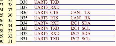
原理图分析 本次学习我们针对 MPU6050 陀螺仪进行开发。根据原理图分析可以得知,在 imx6ul 上 UART4 的 TX、RX 引脚可以复用为 I2C1 的 SCL、SDA线,分别对应板上扩展的42、43接口。
图 7 原理图
MPU6050 常用的设备地址为 0x68。
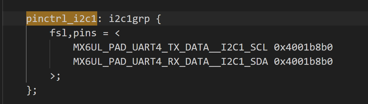
代码编写 1、修改设备树
图 7 设备树IO
**2、在 i2c1 节点追加 mpu6050 子节点,在 &i2c1 下添加子节点:
1
2
3
4
5
6
mpu6050@68 { compatible = "hcw,mpu6050"; reg = <0x68>; vdd-supply = <®_peri_3v3>; vddio-supply = <®_peri_3v3>; };
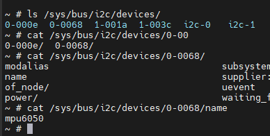
编译设备树并使用最新的 btd 文件启动,可以看到创建设备成功。
图 8 设备节点创建成功
新建文件夹,创建 C 文件,写入以下内容。
1 2 3 4 5 6 7 8 9 10 11 12 13 14 15 16 17 18 19 20 21 22 23 24 25 26 27 28 29 30 31 32 33 34 35 36 37 38 39 40 41 42 43 44 45 46 47 48 49 50 51 52 53 54 55 56 57 58 59 60 61 62 63 64 65 66 67 68 69 70 71 72 73 74 75 76 77 78 79 80 81 82 83 84 85 86 87 88 89 90 91 92 93 94 95 96 97 98 99 100 101 102 103 104 105 106 107 108 109 110 111 112 113 114 115 116 117 118 119 120 121 122 123 124 125 126 127 128 129 130 131 132 133 134 135 136 137 138 139 140 141 142 143 144 145 146 147 148 149 150 151 152 153 154 155 156 157 158 159 160 161 162 163 164 165 166 167 168 169 170 171 172 173 174 175 176 177 178 179 180 181 182 183 184 185 186 187 188 189 190 191 192 193 194 195 196 197 198 199 200 201 202 203 204 205 206 207 208 209 210 211 212 213 214 215 216 217 218 219 220 221 222 223 224 225 226 227 228 229 230 231 232 233 234 235 236 237 #include "mpu6050.h" #include <linux/types.h> #include <linux/kernel.h> #include <linux/delay.h> #include <linux/init.h> #include <linux/module.h> #include <linux/errno.h> #include <linux/gpio.h> #include <linux/cdev.h> #include <linux/device.h> #include <linux/of_gpio.h> #include <linux/semaphore.h> #include <linux/timer.h> #include <linux/i2c.h> #include <asm/mach/map.h> #include <asm/uaccess.h> #include <asm/io.h> #define MPU6050_CNT 1 #define MPU6050_NAME "mpu6050" struct mpu6050_dev { dev_t devid; struct cdev cdev ; struct class *class ; struct device *device ; struct device_node *nd ; int major; void *private_data; u16 acc[3 ],gyr[3 ]; }; static struct mpu6050_dev mpu6050dev ;static int mpu6050_read_regs (struct mpu6050_dev *dev, uint8_t reg, void *val, int len) { int ret; struct i2c_msg msg [2]; struct i2c_client *client =struct i2c_client *)dev->private_data; msg[0 ].addr = client->addr; msg[0 ].flags = 0 ; msg[0 ].buf = ® msg[0 ].len = 1 ; msg[1 ].addr = client->addr; msg[1 ].flags = I2C_M_RD; msg[1 ].buf = val; msg[1 ].len = len; ret = i2c_transfer(client->adapter, msg, 2 ); if (ret == 2 ) { ret = 0 ; } else { printk("i2c rd failed = %d,reg = %06x, len = %d\r\n" ,ret,reg,len); return -EREMOTEIO; } return ret; } static int mpu6050_write_regs (struct mpu6050_dev *dev, u8 reg, u8* buf, int len) { u8 b[256 ]; struct i2c_msg msg ; struct i2c_client *client =struct i2c_client *)dev->private_data; b[0 ] = reg; memcpy (&b[1 ], buf,len); msg.addr = client->addr; msg.buf = b; msg.flags = 0 ; msg.len = len+1 ; return i2c_transfer(client->adapter, &msg, 1 ); } static u8 mpu6050_read_reg (struct mpu6050_dev *dev, u8 reg) { u8 data = 0 ; mpu6050_read_regs(dev, reg, &data, 1 ); return data; } static void mpu6050_write_reg (struct mpu6050_dev *dev, u8 reg, u8 data) { u8 buf = 0 ; buf = data; mpu6050_write_regs(dev, reg, &buf, 1 ); } static void mpu6050_read_data (struct mpu6050_dev *dev) { u8 buf[6 ]; mpu6050_read_regs(dev, MPU6050_GYRO_XOUT_H, buf, 6 ); dev->gyr[0 ] = (buf[0 ] << 8 )|buf[1 ]; dev->gyr[1 ] = (buf[2 ] << 8 )|buf[3 ]; dev->gyr[2 ] = (buf[4 ] << 8 )|buf[5 ]; mpu6050_read_regs(dev, MPU6050_ACCEL_XOUT_H, buf, 6 ); dev->acc[0 ] = (buf[0 ] << 8 )|buf[1 ]; dev->acc[1 ] = (buf[2 ] << 8 )|buf[3 ]; dev->acc[2 ] = (buf[4 ] << 8 )|buf[5 ]; } static int mpu6050_open (struct inode *inode,struct file *filp) { filp->private_data = &mpu6050dev; return 0 ; } static int mpu6050_release (struct inode *inode,struct file *filp) { return 0 ; } static ssize_t mpu6050_read (struct file *filp, char __user *buf, size_t cnt, loff_t *off) { struct mpu6050_dev *dev =struct mpu6050_dev *)filp->private_data; mpu6050_read_data(dev); return 0 ; } static const struct file_operations mpu6050_fops = .owner = THIS_MODULE, .open = mpu6050_open, .release = mpu6050_release, .read = mpu6050_read, }; static int mpu6050_probe (struct i2c_client *client, const struct i2c_device_id *id) { u8 ret = 0 ; if (mpu6050dev.major) { mpu6050dev.major = MKDEV(mpu6050dev.major,0 ); register_chrdev_region(mpu6050dev.devid, MPU6050_CNT, MPU6050_NAME); } else { alloc_chrdev_region(&mpu6050dev.devid,0 , MPU6050_CNT,MPU6050_NAME); mpu6050dev.major = MAJOR(mpu6050dev.major); } cdev_init(&mpu6050dev.cdev, &mpu6050_fops); cdev_add(&mpu6050dev.cdev, mpu6050dev.devid, MPU6050_CNT); mpu6050dev.class = class_create(THIS_MODULE, MPU6050_NAME); if (IS_ERR(mpu6050dev.class)) { return PTR_ERR(mpu6050dev.class); } mpu6050dev.device = device_create(mpu6050dev.class, NULL , mpu6050dev.devid, NULL , MPU6050_NAME); if (IS_ERR(mpu6050dev.device)) { return PTR_ERR(mpu6050dev.device); } mpu6050dev.private_data = client; mdelay(500 ); mpu6050_write_reg(&mpu6050dev, MPU6050_PWR_MGMT_1, 0x00 ); mpu6050_write_reg(&mpu6050dev, MPU6050_SMPLRT_DIV , 0x07 ); mpu6050_write_reg(&mpu6050dev, MPU6050_CONFIG , 0x06 ); mpu6050_write_reg(&mpu6050dev, MPU6050_ACCEL_CONFIG , 0x01 ); mpu6050_write_reg(&mpu6050dev, MPU6050_GYRO_CONFIG, 0x18 ); mdelay(200 ); ret = mpu6050_read_reg(&mpu6050dev, MPU6050_WHO_AM_I); if (ret != 0x68 ) { printk("MPU6050 Init err!\r\n" ); return -ENOENT; } else { printk("MPU6050 Init SUCCESS!\r\n" ); } return 0 ; } static void mpu6050_remove (struct i2c_client *client) { cdev_del(&mpu6050dev.cdev); unregister_chrdev_region(mpu6050dev.devid, MPU6050_CNT); device_destroy(mpu6050dev.class,mpu6050dev.devid); class_destroy(mpu6050dev.class); } static const struct of_device_id mpu6050_of_match [] = {.compatible = "hcw,mpu6050" }, {} }; static struct i2c_driver mpu6050_drv = .probe = mpu6050_probe, .remove = mpu6050_remove, .driver ={ .name = "mpu6050_drv" , .of_match_table = mpu6050_of_match, .owner = THIS_MODULE, }, }; static int __init mpu6050_init (void ) { int ret = 0 ; ret = i2c_add_driver(&mpu6050_drv); return ret; } static void __exit mpu6050_exit (void ) { i2c_del_driver(&mpu6050_drv); } module_init(mpu6050_init); module_exit(mpu6050_exit); MODULE_AUTHOR("hcw" ); MODULE_LICENSE("GPL" );
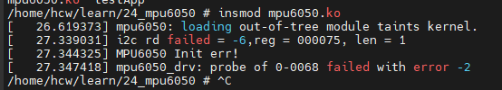
编译出 ko 文件,尝试装载模块,竟然出现了报错:
图 9 I2C 出现报错
询问 AI 得知,在读寄存器 0x75 时,i2c_transfer() 返回了 -6,在内核里就是 -ENXIO,含义通常是:总线上这个地址没有设备应答(NACK)。
我们进一步细分报错,修改 probe 函数。
1
2
3
4
5
6
7
8
9
if (ret < 0 ) return ret; if (id != 0x68 ) return -ENODEV; else { printk("MPU6050 Init SUCCESS!\r\n" ); } return 0 ;
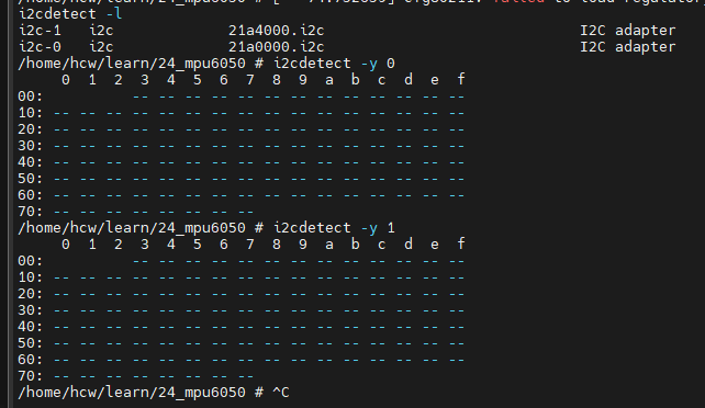
还是出现和刚刚一样的报错,这时我们执行如图所示命令:
图 10 扫描 I2C 设备
i2cdetect -l 可以查看系统里有几条 I2C 总线,i2cdetect -y 2 表示从地址 0x03 开始到 0x77 逐个扫描,如果有这个设备就打印出来。很明显在两条总线上都扫描不到 I2C 设备,那是哪里出问题了呢?
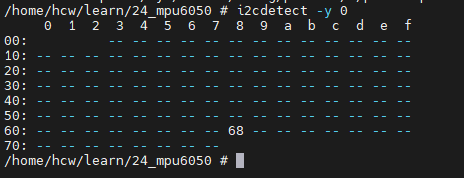
OK啊居然是 SCL 和 SDA 接反了,现在更换过来以后再扫描设备,可以看到 68 了!
图 11 I2C 扫描成功
但是再次尝试装载,又出现了新的报错,我们来分析一下
1
2
3
4
5
6
7
8
9
10
11
12
13
14
15
16
17
18
19
20
21
22
23
24
25
26
27
28
29
30
31
32
/home/hcw/learn/24_mpu6050 # insmod mpu6050.ko [ 663.694123] sysfs: cannot create duplicate filename '/class/mpu6050' [ 663.700569] CPU: 0 PID: 122 Comm: insmod Tainted: G O 6.1.161 #1 [ 663.708016] Hardware name: Freescale i.MX6 Ultralite (Device Tree) [ 663.714237] unwind_backtrace from show_stack+0x10/0x14 [ 663.719544] show_stack from dump_stack_lvl+0x58/0x70 [ 663.724666] dump_stack_lvl from sysfs_warn_dup+0x58/0x64 [ 663.730132] sysfs_warn_dup from sysfs_create_dir_ns+0xf8/0x108 [ 663.736109] sysfs_create_dir_ns from kobject_add_internal+0xa0/0x2e4 [ 663.742621] kobject_add_internal from kset_register+0x6c/0xa0 [ 663.748524] kset_register from __class_register+0xd0/0x170 [ 663.754163] __class_register from __class_create+0x4c/0x74 [ 663.759795] __class_create from mpu6050_probe+0x8c/0x1f4 [mpu6050] [ 663.766159] mpu6050_probe [mpu6050] from i2c_device_probe+0x2c0/0x2d8 [ 663.772783] i2c_device_probe from really_probe+0xc8/0x2ec [ 663.778333] really_probe from __driver_probe_device+0x88/0x1a0 [ 663.784308] __driver_probe_device from driver_probe_device+0x30/0x108 [ 663.790891] driver_probe_device from __driver_attach+0x94/0x184 [ 663.796953] __driver_attach from bus_for_each_dev+0x7c/0xc4 [ 663.802687] bus_for_each_dev from bus_add_driver+0x164/0x1f0 [ 663.808499] bus_add_driver from driver_register+0x88/0x11c [ 663.814129] driver_register from i2c_register_driver+0x40/0xa8 [ 663.820114] i2c_register_driver from do_one_initcall+0x7c/0x2ec [ 663.826189] do_one_initcall from do_init_module+0x44/0x1dc [ 663.831832] do_init_module from sys_init_module+0x150/0x170 [ 663.837565] sys_init_module from ret_fast_syscall+0x0/0x1c [ 663.843196] Exception stack(0xe09f1fa8 to 0xe09f1ff0) [ 663.848294] 1fa0: 00002470 beedae64 00a16220 00002470 000c9e18 00000000 [ 663.856513] 1fc0: 00002470 beedae64 000daefc 00000080 beedae68 beedae6c 00000000 000b4f12 [ 663.864727] 1fe0: beedab08 beedaaf8 0002f23d b6eb59c2 [ 663.870505] kobject_add_internal failed for mpu6050 with -EEXIST, don't try to register things with the same name in the same directory. [ 663.883019] mpu6050_drv: probe of 0-0068 failed with error -17
这段报错表示在 probe 函数中又一次创建了名为 mpu6050 的 class,和之前已经创建的冲突。大概率是因为之前在未扫描到设备时直接 return 了,没有执行 class_destroy 操作。根据 chatgpt 的建议,我们将 class_create 等注册函数放在 模块初始化中,也就是 init,将销毁操作放在 exit 中。在 probe() 里只做 device_create() 和硬件初始化。
根据 chatgpt 的建议,我进一步重构了代码,但还是无法初始化 MPU6050,我们新开一篇日记再战!